Building an IoT Sensor Network with LoRa and ESP32

Are you looking to create an IoT system that operates over long distances, lasts for a long time, and consumes low power?
Then LoRa communication with the ESP32 is an excellent option.
This guide will walk you through setting up a basic LoRa communication system, featuring a base station and sensor nodes to send sensor data to the base station using LoRa.
Components Needed
Base Station
- ESP32 Development Board
- Ra-02 LoRa Module with 433MHz Antenna (for Asia Region)
- 1602 I2C LCD Display
- Push button
- Jumper Wires
Sensor Node
- ESP32 Development Board
- Ra-02 LoRa Module with 433MHz Antenna (for Asia Region)
- Jumper Wires
- JSN SR-04 Ultrasonic Sensor
(Note: Make sure to check the supported LoRa frequency for your region.)
- Asia: 433MHz
- Europe: 868MHz
- North America: 915MHz
Circuit Diagram
First, you’ll need to set up the base station and sensor node using the components listed above. The wiring diagrams for both the base station and sensor node are shown below.
Base Station Wiring Diagram,

Sensor Node Wiring Diagram,

Ensure all connections are correct and secure. Double-check the wiring before powering up or connecting to a computer.
Note: Make sure the antenna is properly connected between the LoRa module and the antenna.
Installing Libraries
Before proceeding, you will need to install two key libraries: The LoRa library for communication and the LiquidCrystal_I2C library for displaying data on an LCD screen.
LoRa Library: The LoRa library provides functions for using LoRa communication with the ESP32. To install it,
- Open the Arduino IDE.
- Go to Sketch > Include Library > Manage Libraries.
- In the Library Manager, search for LoRa.
- Install the library authored by Sandeep Mistry.
LiquidCrystal_I2C Library: The LiquidCrystal_I2C library allows you to easily control an LCD screen via the I2C bus. To install it,
- Go to Sketch > Include Library > Manage Libraries in the Arduino IDE.
- Search for LiquidCrystal_I2C.
- Install the library by Frank de Brabander.
Or else you can download the libraries from the link. Add those libraries into the folder Documents> Arduino> Libraries
Initial Test to Check LoRa Functionality
Once the hardware is set up, let’s implement some basic code to check the functionality of both the base station and the sensor node. Upload the corresponding code to the base station and sensor node.
Note: You will need to adjust the LoRa initialization frequency according to the antenna frequency you are using. If you are using a different frequency than 433MHz, update the following line in the code:
while (!LoRa.begin(433E6))Base Station Test Code
#include <LoRa.h>
#include <SPI.h>

#define ss 5
#define rst 14
#define dio0 2

void setup()
{
  Serial.begin(9600);
  while (!Serial);
  Serial.println("LoRa Receiver");

  LoRa.setPins(ss, rst, dio0);    //setup LoRa transceiver module

  while (!LoRa.begin(433E6))     //433E6 - Asia, 866E6 - Europe, 915E6 - North America
  {
    Serial.println(".");
    delay(500);
  }
  LoRa.setSyncWord(0xA5);
  Serial.println("LoRa Initializing OK!");
}

void loop()
{
  int packetSize = LoRa.parsePacket();    // try to parse packet
  if (packetSize)
  {

    Serial.print("Received packet '");

    while (LoRa.available())              // read packet
    {
      String LoRaData = LoRa.readString();
      Serial.print(LoRaData);
    }
    Serial.print("' with RSSI ");         // print RSSI of packet
    Serial.println(LoRa.packetRssi());
  }
}
Sensor Node Test Code:
#include <LoRa.h>
#include <SPI.h>
#define ss 5
#define rst 14
#define dio0 2
int counter = 0;
void setup()
{
Serial.begin(9600);
while (!Serial);
Serial.println("LoRa Sender");
LoRa.setPins(ss, rst, dio0); //setup LoRa transceiver module
while (!LoRa.begin(433E6)) //433E6 - Asia, 866E6 - Europe, 915E6 - North America
{
Serial.println(".");
delay(500);
}
LoRa.setSyncWord(0xA5);
Serial.println("LoRa Initializing OK!");
}
void loop()
{
Serial.print("Sending packet: ");
Serial.println(counter);
LoRa.beginPacket(); //Send LoRa packet to receiver
LoRa.print("hello ");
LoRa.print(counter);
LoRa.endPacket();
counter++;
delay(2000);
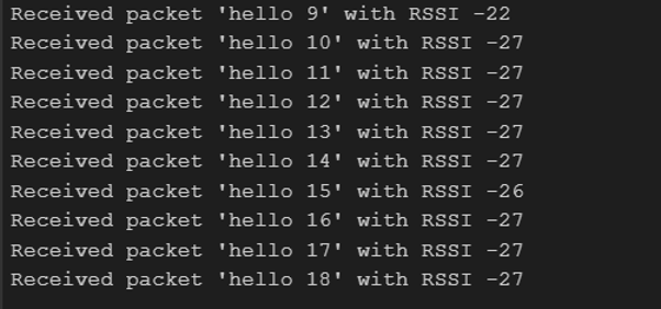
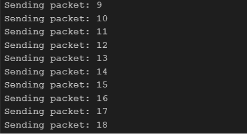
}After uploading the code, you will see below output.
Base Station Results
Sensor Node Results
LoRa Communication System Code with a distance sensor
If the tests are successful, you can proceed by uploading the following code to retrieve data from the JSN-SR04 Ultrasonic Sensor and send it to the base station via LoRa communication.
Base Station Final Code
#include <LoRa.h>
#include <SPI.h>
#include <Wire.h>
#include <LiquidCrystal_I2C.h>

// LoRa pins
#define ss 5
#define rst 14
#define dio0 2

// Button pin
#define buttonPin 15

// Number of nodes
const int numNodes = 3;

// Array to store the latest distance from each node
int nodeDistances[numNodes] = {0};

// I2C LCD setup
LiquidCrystal_I2C lcd(0x27, 16, 2);

// Variables for button and display
volatile int currentNode = -1;
bool buttonPressed = false;
unsigned long lastButtonPress = 0; // Variable for debounce timing
const unsigned long debounceDelay = 500; // 500 milliseconds debounce time

void IRAM_ATTR handleButtonPress() {
  unsigned long currentMillis = millis();

  // Check if enough time has passed since the last button press
  if (currentMillis - lastButtonPress >= debounceDelay) {
    lastButtonPress = currentMillis;
    buttonPressed = true;
  }
}

void setup() {
  // Start Serial communication
  Serial.begin(9600);
  while (!Serial);
  Serial.println("Base Station Starting...");

  // Setup LoRa
  LoRa.setPins(ss, rst, dio0);

  // Initialize LoRa at 433 MHz
  while (!LoRa.begin(433E6)) {
    Serial.println("LoRa Initialization...");
    delay(500);
  }

  LoRa.setSyncWord(0xA5);
  Serial.println("LoRa Initialized!");

  // Initialize LCD
  lcd.init();
  lcd.clear();
  lcd.backlight();      // Make sure backlight is on
  lcd.setCursor(3, 0);
  lcd.print("Press Next");
  lcd.setCursor(5,1);
  lcd.print("Button");

  // Setup button with interrupt
  pinMode(buttonPin, INPUT_PULLUP);
  attachInterrupt(digitalPinToInterrupt(buttonPin), handleButtonPress, FALLING);
}

void loop() {
  int packetSize = LoRa.parsePacket();

  if (packetSize) {
    String receivedData = "";

    while (LoRa.available()) {
      receivedData += (char)LoRa.read();
    }

    Serial.print("Received: ");
    Serial.println(receivedData);
    Serial.print(" | RSSI: ");
    Serial.println(LoRa.packetRssi());

    // Extract node ID and distance
    int nodeId = -1;
    int distance = 0;

    if (sscanf(receivedData.c_str(), "Node %d Distance: %d", &nodeId, &distance) == 2) {
      if (nodeId > 0 && nodeId <= numNodes) {
        nodeDistances[nodeId - 1] = distance;
        Serial.print("Node ");
        Serial.print(nodeId);
        Serial.print(" Distance saved: ");
        Serial.println(distance);
      }
    } else {
      Serial.println("Unknown data format");
    }
  }

  // Handle button press to update the display
  if (buttonPressed) {
    buttonPressed = false;
    currentNode = (currentNode + 1) % numNodes;
    lcd.clear();
    lcd.setCursor(0, 0);
    lcd.print("Node ");
    lcd.print(currentNode + 1);
    lcd.print(" Distance:");
    lcd.setCursor(0, 1);
    lcd.print(nodeDistances[currentNode]);
    lcd.print(" cm");
  }
}
Sensor Node Final Code
#include <LoRa.h>
#include <SPI.h>
// Ultrasonic sensor pins
#define echoPin 27 // GPIO27 connected to Echo pin of JSN-SR04
#define trigPin 26 // GPIO26 connected to Trig pin of JSN-SR04
// LoRa pins
#define ss 5
#define rst 14
#define dio0 2
long duration;
int distance;
int nodeID = 1; // Unique ID for Sensor Node 1
void setup() {
// Initialize sensor pins
pinMode(trigPin, OUTPUT);
pinMode(echoPin, INPUT);
// Start Serial communication
Serial.begin(9600);
Serial.println("Sensor Node 1 Starting...");
// Setup LoRa
LoRa.setPins(ss, rst, dio0);
// Initialize LoRa at 433 MHz
while (!LoRa.begin(433E6)) {
Serial.println("LoRa Initialization...");
delay(500);
}
LoRa.setSyncWord(0xA5);
Serial.println("LoRa Initialized!");
}
void loop() {
// Measure distance
digitalWrite(trigPin, LOW);
delayMicroseconds(2);
digitalWrite(trigPin, HIGH);
delayMicroseconds(10);
digitalWrite(trigPin, LOW);
duration = pulseIn(echoPin, HIGH);
distance = duration * 0.0344 / 2;
Serial.print("Node ");
Serial.print(nodeID);
Serial.print(" Distance: ");
Serial.print(distance);
Serial.println(" cm");
// Check if distance is greater than 20 cm
if (distance > 20) {
// Send distance via LoRa
Serial.print("Node ");
Serial.print(nodeID);
Serial.print(" Sending distance: ");
Serial.print(distance);
Serial.println(" cm");
LoRa.beginPacket();
LoRa.print("Node ");
LoRa.print(nodeID);
LoRa.print(" Distance: ");
LoRa.print(distance);
LoRa.endPacket();
}
delay(2000); // Wait for 2 seconds
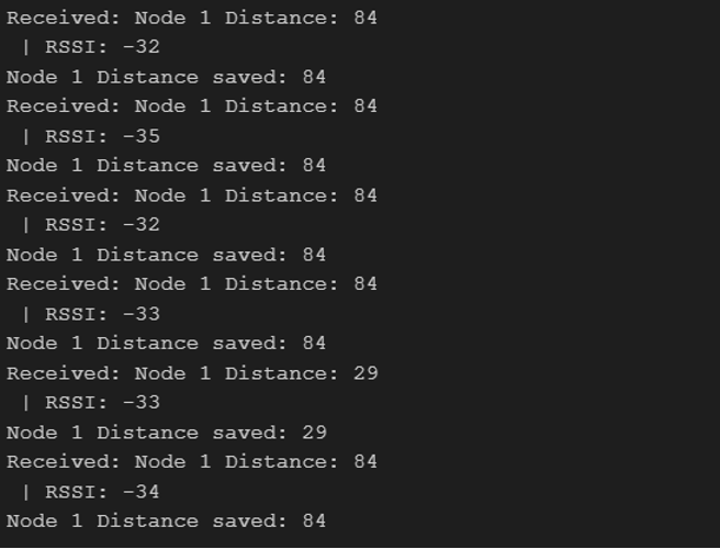
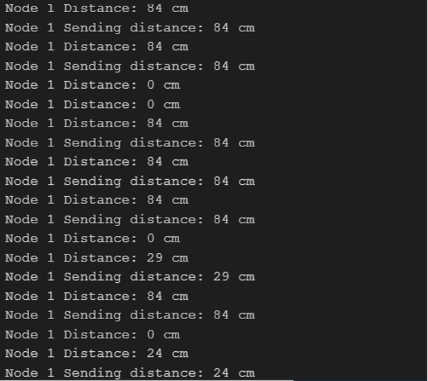
}Final Results
Base Station Final Results
Sensor Node Final Results
Now you can expand the number of nodes and connect multiple nodes with a base station.
On the LCD you will see the following, when button is clicked

Conclusion
LoRa communication is a powerful technology that allows you to build IoT systems with long-range connectivity and low power consumption.
Using the ESP32 and LoRa modules, you can set up an efficient communication system between a base station and multiple sensor nodes.
By following the steps outlined in this guide, you can easily implement this system and modify it for various applications, such as environmental monitoring, remote sensing, and smart agriculture.
With its flexibility and reliability, LoRa can significantly expand the possibilities for your IoT projects.
Hope you enjoyed the article. Please comment below or send us an email to info@protonest.co, if you face any issues when implementing.
Contact us for any consultations or projects related to IoT and embedded systems.
Email: info@protonest.co
Protonest for more details.
Protonest specializes in transforming IoT ideas into reality. We offer prototyping services from concept to completion. Our commitment ensures that your visionary IoT concepts become tangible, innovative, and advanced prototypes.
Our Website: https://www.protonest.co/
Cheers!